三维计算机图形可在平面显示器上提供三维物体的印象。 这样的物体,以及观察者的位置可随时间变化。 相应地,二维图像也应变化,从而生成图像深度的错觉,即,它应该支持旋转、缩放、光照变化、等等。 MQL5 允许利用 DirectX 函数 在 MetaTrader 5 终端里直接创建和管理计算机图形。 请注意,您的显卡应支持 DX 11 和 Shader Model 5.0 才能正常工作。
若要在平面空间上绘制三维物体,应首先得到 X、Y 和 Z 轴坐标上的物体模型。 这意味着物体表面上的每个点均要以特定坐标定义。 理想情况下,需要定义物体表面上的无数个点,从而在缩放图像时保持品质。 实际上,3D 建模是以多边形组成的网模来定义。 多边形端点越多,则网模越详尽,提供的模型越加真实。 然而,计算这样的模型和渲染 3D 图形需要更多的计算机资源。
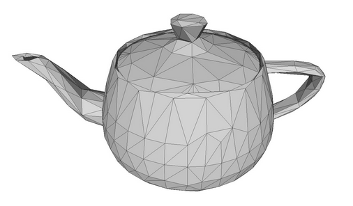
以茶壶模型作为多边形网模。
早期的计算机图形不得不在较弱的图形卡上运行,故将多边形切分成三角形很久以前就出现了。 三角形可精确描述小表面部件的位置,以及计算相关参数,例如光照和光线反射。 这样的小三角形的集合能够创建逼真的物体三维图像。 在下文中,多边形和三角形将归并为同义词,因为想象三角形较之拥有 N 个顶点的多边形,显然容易得多。

由三角形组成的立方体。
按照三角形每个顶点的坐标定义来创建物体的三维模型,如此,即便物体移动或观察者的位置发生变化,也可以进一步计算物体每个点的坐标。 所以,我们要处理的是顶点,连接顶点的边线,以及由边线形成的表面。 如果知道三角形的位置,则可以利用线性代数定律来创建切面法线(法线是垂直于表面的向量)。 如此即可计算出切面如何光照,以及光线如何从切面反射。
简单物体的顶点、边线、切面和法线的示例。 法线是红色箭头。
物体模型能够以不同方式来创建。 拓扑学描述了多边形如何形成 3D 网模。 良好的拓扑结构允许利用最少数量的多边形来描绘对象,并可令物体的移动和旋转更加容易。

两种拓扑中的球面模型。
在物体多边形上利用光影来创建体积效果。 因此,3D 计算机图形的目的是计算物体每个点的位置,计算光线明暗,并将其显示在屏幕上。
我们编写一个创建立方体的简单程序。 利用 3D 图形库中的 CCanvas3D 类。
渲染 3D 窗体的 CCanvas3DWindow 类拥有最少的成员和方法。 我们将逐步添加新方法,并针对操控 DirectX 函数中所实现的 3D 图形概念加以解释。
//+------------------------------------------------------------------+
//| Application window                                               |
//+------------------------------------------------------------------+
class CCanvas3DWindow
  {
protected:
   CCanvas3D         m_canvas;
   //--- canvas size
   int               m_width;
   int               m_height;
   //--- the Cube object
   CDXBox            m_box;

public:
                     CCanvas3DWindow(void) {}
                    ~CCanvas3DWindow(void) {m_box.Shutdown();}
   //-- create a scene
   virtual bool      Create(const int width,const int height){}
   //--- calculate the scene
   void              Redraw(){}
   //--- handle chart events
   void              OnChartChange(void) {}
  };
场景的创建要从创建画布开始。 然后为投影矩阵设置以下参数:
这意味着仅在投影矩阵中渲染物体处于两堵虚构墙面(0.1f 和 100.f)之间的部分。 另外,物体必须落入视角的水平 30 度夹角。 请注意,距离以及计算机图形中的所有坐标都是虚构的。 重要的是距离和大小之间的相对关系,而不是绝对值。
   //+------------------------------------------------------------------+
   //| Create                                                           |
   //+------------------------------------------------------------------+
   virtual bool      Create(const int width,const int height)
     {
      //--- save canvas dimensions
      m_width=width;
      m_height=height;
      //--- create a canvas to render a 3D scene
      ResetLastError();
      if(!m_canvas.CreateBitmapLabel("3D Sample_1",0,0,m_width,m_height,COLOR_FORMAT_ARGB_NORMALIZE))
        {
         Print("Error creating canvas: ",GetLastError());
         return(false);
         }
      //--- set projection matrix parameters - angle of view, aspect ratio, distance to the near and far clip planes
      m_canvas.ProjectionMatrixSet((float)M_PI/6,(float)m_width/m_height,0.1f,100.0f);
      //--- create cube - pass to it the resource manager, scene parameters and coordinates of two opposite corners of the cube
      if(!m_box.Create(m_canvas.DXDispatcher(),m_canvas.InputScene(),DXVector3(-1.0,-1.0,5.0),DXVector3(1.0,1.0,7.0)))
        {
         m_canvas.Destroy();
         return(false);
         }
      //--- add the cube to the scene
      m_canvas.ObjectAdd(&m_box);
      //--- redraw the scene
      Redraw();
      //--- succeed
      return(true);
      }
创建投影矩阵后,我们可以继续构建 3D 物体 — 基于 CDXBox 类的立方体。 为了创建一个立方体,指定立方体两个对角的顶点即可。 通过在调试模式下观察立方体的创建,您可以看到 DXComputeBox() 中所发生的情况:创建立方体的所有顶点(它们的坐标已写入 “vertices” 数组),以及把立方体边线切分为三角形,列举并保存在 “indiсes” 数组当中。 立方体总共有 8 个顶点,6 个切面切分为 12 个三角形,这些三角形顶点列举为 36 个索引。
尽管立方体只有 8 个顶点,但由于要为 6 个切面中的每条法线指定单独的顶点集合,所以创建了 24 个顶点来描述它们。 法线方向会影响每个切面的光照计算。 三角形顶点在索引中的列举顺序决定了可见的三角形边线。 在 DXUtils.mqh 代码里展示了顶点和索引的填充顺序:
   for(int i=20; i<24; i++)
      vertices[i].normal=DXVector4(0.0,-1.0,0.0,0.0);
在同一代码里为每个切面的纹理映射定义了纹理坐标:
//--- texture coordinates
   for(int i=0; i<faces; i++)
     {
      vertices[i*4+0].tcoord=DXVector2(0.0f,0.0f);
      vertices[i*4+1].tcoord=DXVector2(1.0f,0.0f);
      vertices[i*4+2].tcoord=DXVector2(1.0f,1.0f);
      vertices[i*4+3].tcoord=DXVector2(0.0f,1.0f);
      }
4 个切面顶点中的每一个都设置了 4 个角度的纹理映射。 这意味着每个立方体切面在渲染纹理时都会映射一小队结构。 当然,只在设置纹理的情况下才需要这样做。
每次切换 3D 场景时,都应重新执行所有计算。 这是所需计算的顺序:
   //+------------------------------------------------------------------+
   //| Update the scene                                                 |
   //+------------------------------------------------------------------+
   void              Redraw()
     {
      //--- calculate the 3D scene
      m_canvas.Render(DX_CLEAR_COLOR|DX_CLEAR_DEPTH,ColorToARGB(clrBlack));
      //--- update the picture on the canvas in accordance with the current scene
      m_canvas.Update();
      }
在我们的示例中,立方体仅创建一次,且不会再更改。 所以,仅当图表中有变化,诸如调整图表大小时,才需要更改画布上的框架。 在这种情况下,画布维度将调整为当前图表维度,投影矩阵被重置,而画布上的图像亦被更新。
   //+------------------------------------------------------------------+
   //| Process chart change event                                       |
   //+------------------------------------------------------------------+
   void              OnChartChange(void)
     {
      //--- get current chart sizes
      int w=(int)ChartGetInteger(0,CHART_WIDTH_IN_PIXELS);
      int h=(int)ChartGetInteger(0,CHART_HEIGHT_IN_PIXELS);
      //--- update canvas dimensions in accordance with the chart size
      if(w!=m_width || h!=m_height)
        {
         m_width =w;
         m_height=h;
         //--- resize canvas
         m_canvas.Resize(w,h);
         DXContextSetSize(m_canvas.DXContext(),w,h);
         //--- update projection matrix in accordance with the canvas sizes
         m_canvas.ProjectionMatrixSet((float)M_PI/6,(float)m_width/m_height,0.1f,100.0f);
         //--- recalculate 3D scene and render it onto the canvas
         Redraw();
         }
      }
启动 "Step1 Create Box.mq5" EA。 您在黑色背景上会看到一个白色正方形。 默认情况下,创建时物体的颜色设置为白色。 尚未设置光照。
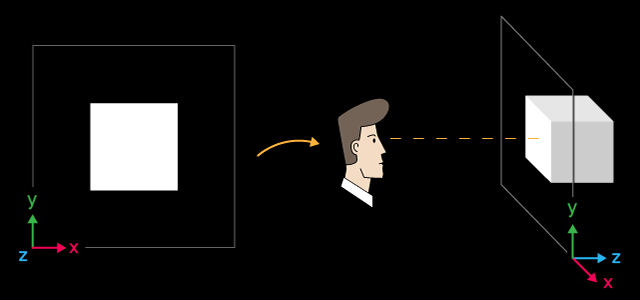
白色立方体及其空间布局
X 轴指向右侧,Y 轴指向上方,Z 轴指向 3D 场景内里。 这种坐标系称为左手系。
立方体的中心位于以下坐标 X=0,Y=0,Z=6 的点上。 从我们的观察来看,立方体位于坐标中心,这是默认值。 如果您要更改 3D 场景的观察点位置,需利用 ViewPositionSet() 函数显性设置相应的坐标。
为了结束程序操作,请按 “Escape(退出)”健。
若为制作场景动画,我们需启用围绕 Z 轴的立方体旋转。 为此,添加一个计时器 — 基于其事件,立方体将以逆时针旋转。
利用 DXMatrixRotationZ() 方法创建一个按给定角度围绕 Z 轴旋转的矩阵。 然后将其作为参数传递给 TransformMatrixSet() 方法。 如此即可更改立方体在 3D 空间中的位置。 再者,调用 Redraw() 刷新画布上的图像。
   //+------------------------------------------------------------------+
   //| Timer handler                                                    |
   //+------------------------------------------------------------------+
   void              OnTimer(void)
     {
      //--- variables for calculating the rotation angle
      static ulong last_time=0;
      static float angle=0;
      //--- get the current time
      ulong current_time=GetMicrosecondCount();
      //--- calculate the delta
      float deltatime=(current_time-last_time)/1000000.0f;
      if(deltatime>0.1f)
         deltatime=0.1f;
      //--- increase the angle of rotation of the cube around the Z axis
      angle+=deltatime;
      //--- remember the time
      last_time=current_time;
      //--- set the angle of rotation of the cube around the Z axis
      DXMatrix rotation;
      DXMatrixRotationZ(rotation,angle);
      m_box.TransformMatrixSet(rotation);
      //--- recalculate 3D scene and render it onto the canvas
      Redraw();
      }
启动后,您会看到一个旋转的白色正方形。
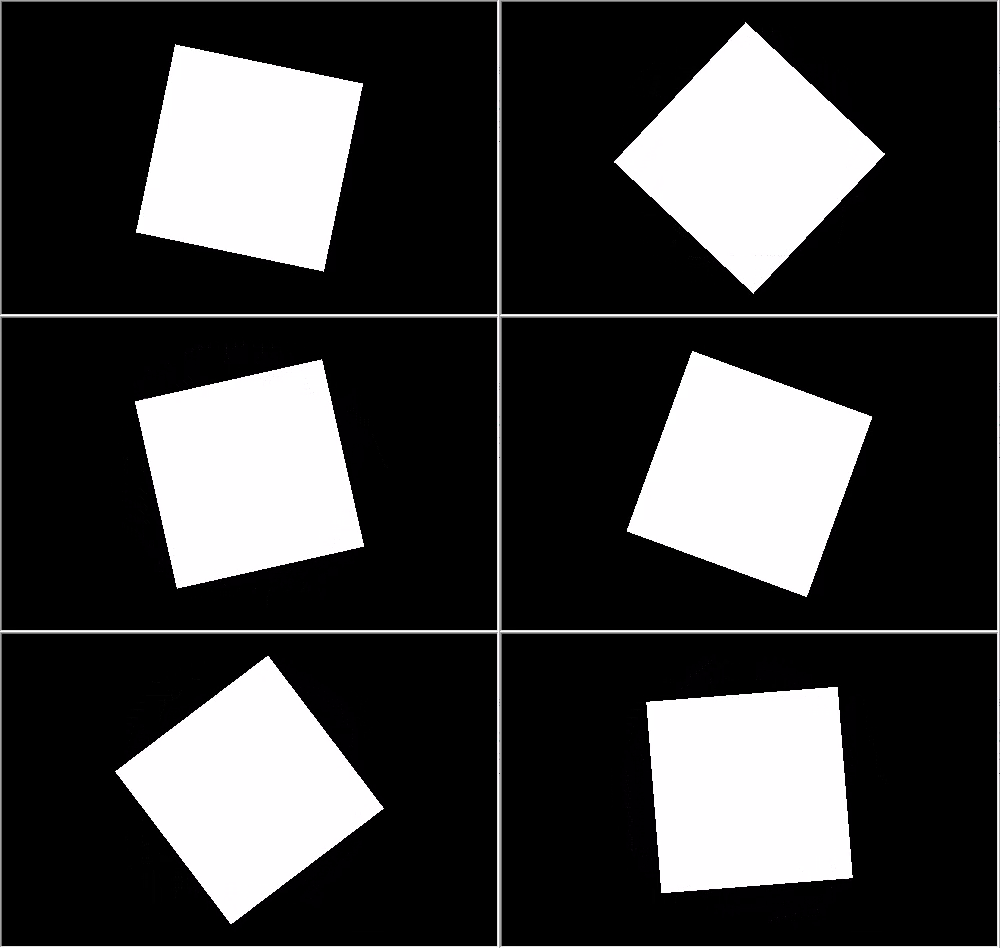
立方体绕 Z 轴逆时针旋转
该示例的源代码在文件 “Step2 Rotation Z.mq5” 中提供。 请注意,创建场景时现已指定了角度 M_PI/5,该角度大于前一个示例的角度 M_PI/6。
      //--- set projection matrix parameters - angle of view, aspect ratio, distance to the near and far clip planes
      m_matrix_view_angle=(float)M_PI/5;
      m_canvas.ProjectionMatrixSet(m_matrix_view_angle,(float)m_width/m_height,0.1f,100.0f);
      //--- create cube - pass to it the resource manager, scene parameters and coordinates of two opposite corners of the cube
然而,场景里的立方体维度在视觉上较小。 设置投影矩阵时指定的视角越小,则物体边框占据的部分越大。 这好比用望远镜观看物体:尽管视角较小,但物体较大。
CCanvas3D 类拥有三个设置重要 3D 场景参数的方法,这些方法相互关联:
所有这些参数会被组合使用 — 这意味着,如果您要在 3D 场景中设置这些参数中的任何一个,则其他两个参数也必须要初始化。 至少应在场景生成阶段完成此操作。 这一点在下面的示例中有所展示,其框架的上边框左右摆动。 摆动是在 Create() 方法中添加以下三行代码来实现的:
   //+------------------------------------------------------------------+
   //| Create                                                           |
   //+------------------------------------------------------------------+
   virtual bool      Create(const int width,const int height)
     {
....
      //--- add the cube to the scene
      m_canvas.ObjectAdd(&m_box);
      //--- set the scene parameters
      m_canvas.ViewUpDirectionSet(DXVector3(0,1,0));  // set the direction vector up, along the Y axis
      m_canvas.ViewPositionSet(DXVector3(0,0,0));     // set the viewpoint from the center of coordinates
      m_canvas.ViewTargetSet(DXVector3(0,0,6));       // set the gaze point at center of the cube
      //--- redraw the scene
      Redraw();
      //--- succeed
      return(true);
      }
修改 OnTimer() 方法令顶点左右水平摆动。
   //+------------------------------------------------------------------+
   //| Timer handler                                                    |
   //+------------------------------------------------------------------+
   void              OnTimer(void)
     {
      //--- variables for calculating the rotation angle
      static ulong last_time=0;
      static float max_angle=(float)M_PI/30;
      static float time=0;
      //--- get the current time
      ulong current_time=GetMicrosecondCount();
      //--- calculate the delta
      float deltatime=(current_time-last_time)/1000000.0f;
      if(deltatime>0.1f)
         deltatime=0.1f;
      //--- increase the angle of rotation of the cube around the Z axis
      time+=deltatime;
      //--- remember the time
      last_time=current_time;
      //--- set the rotation angle around the Z axis
      DXVector3 direction=DXVector3(0,1,0);     // initial direction of the top
      DXMatrix rotation;                        // rotation vector
      //--- calculate the rotation matrix
      DXMatrixRotationZ(rotation,float(MathSin(time)*max_angle));
      DXVec3TransformCoord(direction,direction,rotation);
      m_canvas.ViewUpDirectionSet(direction);   // set the new direction of the top
      //--- recalculate 3D scene and render it onto the canvas
      Redraw();
      }
将示例另存为 “Step3 ViewUpDirectionSet.mq5” 并运行它。 您将看到一个旋转的立方体图像,尽管它实际上是静止的。 当相机本身左右摆动时,就会得到这种效果。
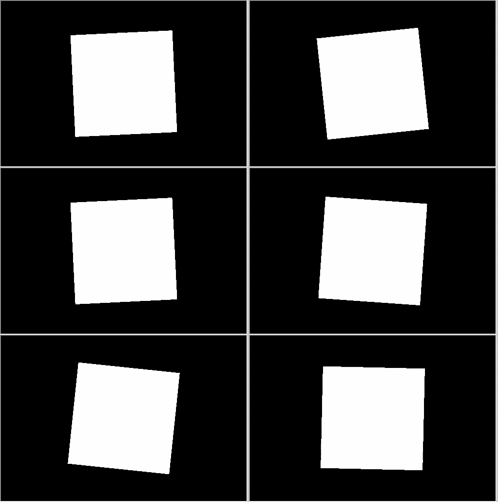
顶部方向左右摆动
我们来修改代码,然后在移动相机的同时将立方体放在坐标中心。
   //+------------------------------------------------------------------+
   //| Create                                                           |
   //+------------------------------------------------------------------+
   virtual bool      Create(const int width,const int height)
     {
  ...
      //--- create cube - pass to it the resource manager, scene parameters and coordinates of two opposite corners of the cube
      if(!m_box.Create(m_canvas.DXDispatcher(),m_canvas.InputScene(),DXVector3(-1.0,-1.0,-1.0),DXVector3(1.0,1.0,1.0)))
        {
         m_canvas.Destroy();
         return(false);
         }
      //--- set the color
      m_box.DiffuseColorSet(DXColor(0.0,0.5,1.0,1.0));
      //--- add the cube to the scene
      m_canvas.ObjectAdd(&m_box);
      //--- set positions for camera, gaze and direction of the top
      m_canvas.ViewUpDirectionSet(DXVector3(0.0,1.0,0.0));  // set the direction vector up, along the Y axis
      m_canvas.ViewPositionSet(DXVector3(3.0,2.0,-5.0));    // set camera on the right, on top and in front of the cube
      m_canvas.ViewTargetSet(DXVector3(0,0,0));             // set the gaze direction at center of the cube
      //--- redraw the scene
      Redraw();
      //--- succeed
      return(true);
      }
此外,将立方体染成蓝色。 颜色是以含 Alpha 通道的 RGB 格式设置(Alpha 通道在末尾),且数值已被归一化。 因此,数值 1 表示 255,而数值 0.5 表示 127。
添加围绕 X 轴的旋转,并保存修改为 “Step4 Box Color.mq5”。
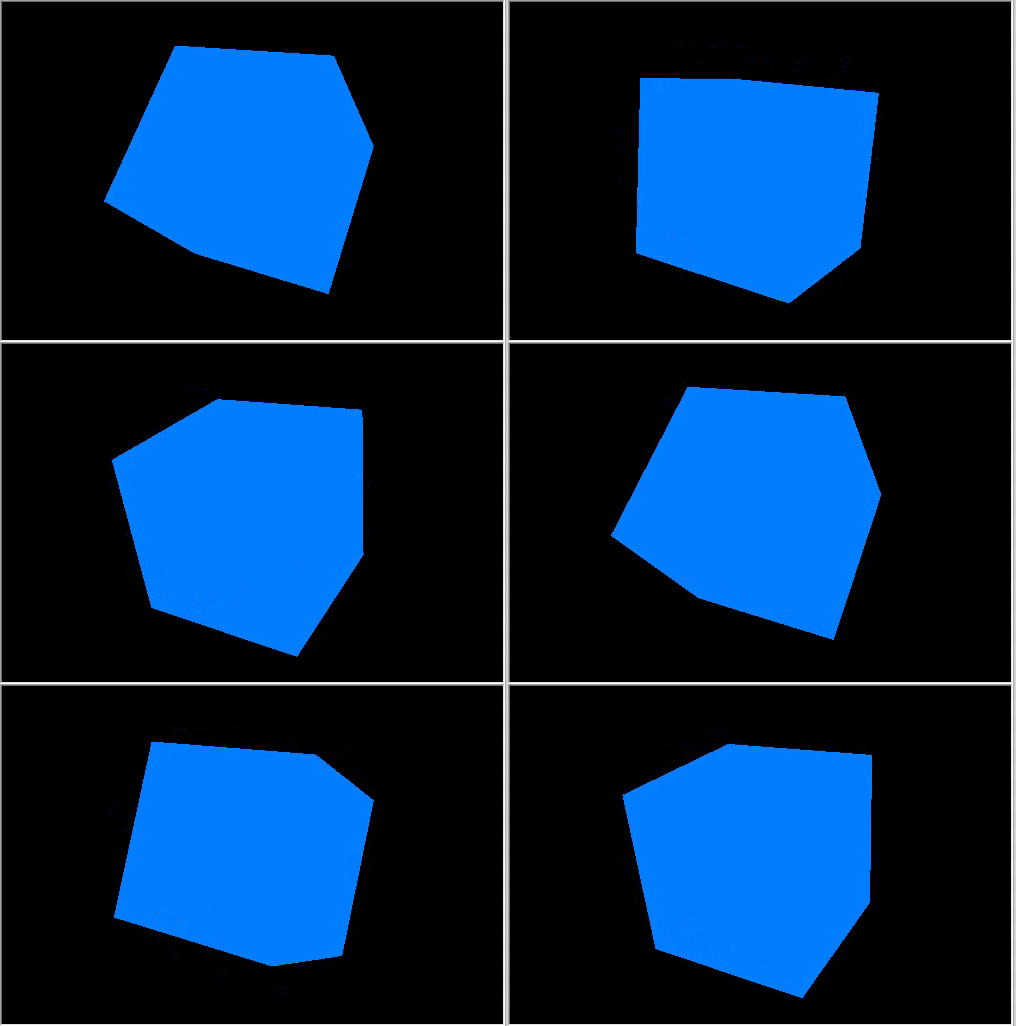
旋转立方体的右上视图。
可以一次在三个方向上移动和旋转物体。 物体的所有更改均使用矩阵实现。 它们中的每一个,即旋转、移动和变换,均可分别计算。 我们来修改示例:相机视野现在从顶部到前面。
   //+------------------------------------------------------------------+
   //| Create                                                           |
   //+------------------------------------------------------------------+
   virtual bool      Create(const int width,const int height)
     {
  ...
      m_canvas.ProjectionMatrixSet(m_matrix_view_angle,(float)m_width/m_height,0.1f,100.0f);
      //--- position the camera in top and in front of the center of coordinates
      m_canvas.ViewPositionSet(DXVector3(0.0,2.0,-5.0));
      m_canvas.ViewTargetSet(DXVector3(0.0,0.0,0.0));
      m_canvas.ViewUpDirectionSet(DXVector3(0.0,1.0,0.0));
      //--- create cube - pass to it the resource manager, scene parameters and coordinates of two opposite corners of the cube
      if(!m_box.Create(m_canvas.DXDispatcher(),m_canvas.InputScene(),DXVector3(-1.0,-1.0,-1.0),DXVector3(1.0,1.0,1.0)))
        {
         m_canvas.Destroy();
         return(false);
         }
      //--- set the cube color
      m_box.DiffuseColorSet(DXColor(0.0,0.5,1.0,1.0));
      //--- calculate the cube position and the transfer matrix
      DXMatrix rotation,translation;
      //--- rotate the cube sequentially along the X, Y and Z axes
      DXMatrixRotationYawPitchRoll(rotation,(float)M_PI/4,(float)M_PI/3,(float)M_PI/6);
      //-- move the cube to the right/downward/inward
      DXMatrixTranslation(translation,1.0,-2.0,5.0);
      //--- get the transformation matrix as a product of rotation and transfer
      DXMatrix transform;
      DXMatrixMultiply(transform,rotation,translation);
      //--- set the transformation matrix
      m_box.TransformMatrixSet(transform);
      //--- add the cube to the scene
      m_canvas.ObjectAdd(&m_box);
      //--- redraw the scene
      Redraw();
      //--- succeed
      return(true);
      }
依次创建旋转矩阵和转换矩阵,应用生成的变换矩阵,并渲染立方体。 将修改保存在 "Step5 Translation.mq5",并运行它。
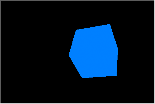
立方体的旋转和运动
依旧是相机,从上方稍微指向坐标中心。 立方体在三个方向上旋转,并向右、向下和向场景内偏移。
为了获得逼真的三维图像,必须计算物体表面上每个点的光照。 这可利用 Phong 着色模型来完成,该模型计算以下三个光照成份的颜色强度:环境、漫反射和镜面反射。 在此采用以下参数:

Phong 着色模型
光照模型在标准着色器中实现,模型参数在 CCanvas3D 中设置,物体参数在 CDXMesh 及其子类中设置。 如下所示修改示例:
      //--- set yellow color for the source and direct it from above downwards
      m_canvas.LightColorSet(DXColor(1.0,1.0,0.0,0.8f));
      m_canvas.LightDirectionSet(DXVector3(0.0,-1.0,0.0));
      //--- set the blue color for the ambient light
      m_canvas.AmbientColorSet(DXColor(0.0,0.0,1.0,0.4f));
      //--- create cube - pass to it the resource manager, scene parameters and coordinates of two opposite corners of the cube
      if(!m_box.Create(m_canvas.DXDispatcher(),m_canvas.InputScene(),DXVector3(-1.0,-1.0,-1.0),DXVector3(1.0,1.0,1.0)))
        {
         m_canvas.Destroy();
         return(false);
         }
      //--- set the white color for the cube
      m_box.DiffuseColorSet(DXColor(1.0,1.0,1.0,1.0));
      //--- add green glow for the cube (emission)
      m_box.EmissionColorSet(DXColor(0.0,1.0,0.0,0.2f));
请注意,在 Canvas3D 中未设置定向光源的位置,而是仅给出了光照的传播方向。 定向光源被认为是无限远的,且照亮场景的是严格的平行光线。
m_canvas.LightDirectionSet(DXVector3(0.0,-1.0,0.0));
此处,光线传播矢量沿 Y 轴指向负数值方向,即从顶部向下。 甚或,如果您为定向光源设置了参数(LightColorSet 和 LightDirectionSet),则还必须指定环境光的颜色(AmbientColorSet)。 默认情况下,环境光的颜色设置为强度最大的白色,因此所有阴影均为白色。 这意味着场景中的物体会被环境光染成白色泛光,而定向光源将被白光打断。
      //--- set yellow color for the source and direct it from above downwards
      m_canvas.LightColorSet(DXColor(1.0,1.0,0.0,0.8f));
      m_canvas.LightDirectionSet(DXVector3(0.0,-1.0,0.0));
      //--- set the blue color for the ambient light
      m_canvas.AmbientColorSet(DXColor(0.0,0.0,1.0,0.4f));  // must be specified
下面的 gif 动画展示了添加光照后的图像变化。 该示例的源代码在文件 “Step6 Add Light.mq5” 中提供。
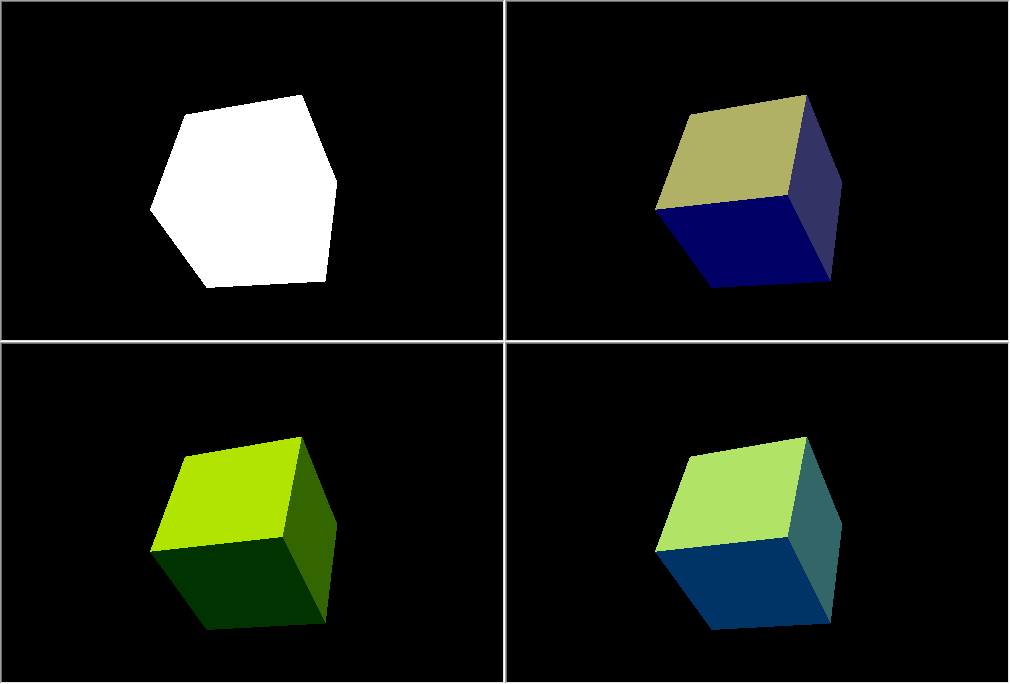
白色立方体,在黄色光源,,蓝色环境光下发出绿光
尝试屏蔽上面代码中的颜色方法,看看它是如何工作的。
动画意味着场景参数和物体随时间变化。 可以根据时间或事件更改任何可用的属性。 将计时器设置为 10 毫秒 — 此事件将影响场景的刷新:
int OnInit()
  {
...
//--- create canvas
   ExtAppWindow=new CCanvas3DWindow();
   if(!ExtAppWindow.Create(width,height))
      return(INIT_FAILED);
//--- set timer
   EventSetMillisecondTimer(10);
//---
   return(INIT_SUCCEEDED);
   }
将相应的事件处理程序添加到 CCanvas3DWindow。 我们需要更改物体参数(诸如旋转、移动和缩放)和光照方向:
   //+------------------------------------------------------------------+
   //| Timer handler                                                    |
   //+------------------------------------------------------------------+
   void              OnTimer(void)
     {
      static ulong last_time=0;
      static float time=0;
      //--- get the current time
      ulong current_time=GetMicrosecondCount();
      //--- calculate the delta
      float deltatime=(current_time-last_time)/1000000.0f;
      if(deltatime>0.1f)
         deltatime=0.1f;
      //--- increase the elapsed time value
      time+=deltatime;
      //--- remember the time
      last_time=current_time;
      //--- calculate the cube position and the rotation matrix
      DXMatrix rotation,translation,scale;
      DXMatrixRotationYawPitchRoll(rotation,time/11.0f,time/7.0f,time/5.0f);
      DXMatrixTranslation(translation,(float)sin(time/3),0.0,0.0);
      //--- calculate the cube compression/extension along the axes
      DXMatrixScaling(scale,1.0f+0.5f*(float)sin(time/1.3f),1.0f+0.5f*(float)sin(time/1.7f),1.0f+0.5f*(float)sin(time/1.9f));
      //--- multiply the matrices to obtain the final transformation
      DXMatrix transform;
      DXMatrixMultiply(transform,scale,rotation);
      DXMatrixMultiply(transform,transform,translation);
      //--- set the transformation matrix
      m_box.TransformMatrixSet(transform);
      //--- calculate the rotation of the light source around the Z axis
      DXMatrixRotationZ(rotation,deltatime);
      DXVector3 light_direction;
      //--- get the current direction of the light source
      m_canvas.LightDirectionGet(light_direction);
      //--- calculate the new direction of the light source and set it
      DXVec3TransformCoord(light_direction,light_direction,rotation);
      m_canvas.LightDirectionSet(light_direction);
      //--- recalculate the 3D scene and draw it in the canvas
      Redraw();
      }
请注意,物体变化将应用于初始值,就像我们始终在处理立方体状态,并从草创开始相对于旋转/移动/缩放等应用所有操作一样,意即立方体的当前状态不会被保存。 不过,光源方向从当前值开始以 deltatime 为增量进行更改。
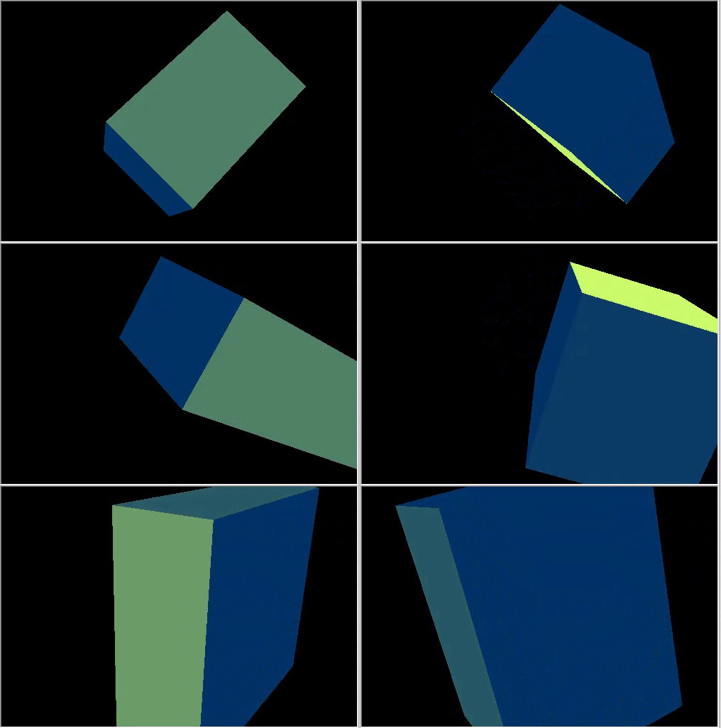
动态光源方向变化的旋转立方体。
结果是一个非常复杂的 3D 动画。 示例代码在文件 “Step7 Animation.mq5” 中提供。
我们来研究 3D 图形的最后一个动画元素,反馈用户的动作。 在我们的示例中,加入利用鼠标管理相机。 首先,订阅鼠标事件,并创建相应的处理程序:
int OnInit()
  {
...
//--- set the timer
   EventSetMillisecondTimer(10);
//--- enable receiving of mouse events: moving and button clicks
   ChartSetInteger(0,CHART_EVENT_MOUSE_MOVE,1);
   ChartSetInteger(0,CHART_EVENT_MOUSE_WHEEL,1)
//---
   return(INIT_SUCCEEDED);
   }
void OnDeinit(const int reason)
  {
//--- Deleting the timer
   EventKillTimer();
//--- disable the receiving of mouse events
   ChartSetInteger(0,CHART_EVENT_MOUSE_MOVE,0);
   ChartSetInteger(0,CHART_EVENT_MOUSE_WHEEL,0);
//--- delete the object
   delete ExtAppWindow;
//--- return chart to the usual display mode with price charts
   ChartSetInteger(0,CHART_SHOW,true);
   }
void OnChartEvent(const int id,const long &lparam,const double &dparam,const string &sparam)
  {
...
//--- chart change event
   if(id==CHARTEVENT_CHART_CHANGE)
      ExtAppWindow.OnChartChange();
//--- mouse movement event
   if(id==CHARTEVENT_MOUSE_MOVE)
      ExtAppWindow.OnMouseMove((int)lparam,(int)dparam,(uint)sparam);
//--- mouse wheel scroll event
   if(id==CHARTEVENT_MOUSE_WHEEL)
      ExtAppWindow.OnMouseWheel(dparam);
在 CCanvas3DWindow 中,创建鼠标移动事件处理程序。 按住鼠标左键并移动鼠标时,它会改变相机的方向角度:
   //+------------------------------------------------------------------+
   //| Handle mouse movements                                           |
   //+------------------------------------------------------------------+
   void              OnMouseMove(int x,int y,uint flags)
     {
      //--- left mouse button
      if((flags&1)==1)
        {
         //--- there is no information about the previous mouse position
         if(m_mouse_x!=-1)
           {
            //--- update the camera angle upon change of position
            m_camera_angles.y+=(x-m_mouse_x)/300.0f;
            m_camera_angles.x+=(y-m_mouse_y)/300.0f;
            //--- set the vertical angle in the range between (-Pi/2,Pi2)
            if(m_camera_angles.x<-DX_PI*0.49f)
               m_camera_angles.x=-DX_PI*0.49f;
            if(m_camera_angles.x>DX_PI*0.49f)
               m_camera_angles.x=DX_PI*0.49f;
            //--- update camera position
            UpdateCameraPosition();
            }
         //--- save mouse position
         m_mouse_x=x;
         m_mouse_y=y;
         }
      else
        {
         //--- reset the saved position if the left mouse button is not pressed
         m_mouse_x=-1;
         m_mouse_y=-1;
         }
      }
这是鼠标滚轮事件的处理程序,其内更改相机和场景中心之间的距离:
   //+------------------------------------------------------------------+
   //| Handling mouse wheel events                                      |
   //+------------------------------------------------------------------+
   void              OnMouseWheel(double delta)
     {
      //--- update the distance between the camera and the center upon a mouse scroll
      m_camera_distance*=1.0-delta*0.001;
      //--- set the distance in the range between [3,50]
      if(m_camera_distance>50.0)
         m_camera_distance=50.0;
      if(m_camera_distance<3.0)
         m_camera_distance=3.0;
      //--- update camera position
      UpdateCameraPosition();
      }
两个处理程序均调用 UpdateCameraPosition() 方法,从而根据更新后的参数变更相机位置:
   //+------------------------------------------------------------------+
   //| Updates the camera position                                      |
   //+------------------------------------------------------------------+
   void              UpdateCameraPosition(void)
     {
      //--- the position of the camera taking into account the distance to the center of coordinates
      DXVector4 camera=DXVector4(0.0f,0.0f,-(float)m_camera_distance,1.0f);
      //--- camera rotation around the X axis
      DXMatrix rotation;
      DXMatrixRotationX(rotation,m_camera_angles.x);
      DXVec4Transform(camera,camera,rotation);
      //--- camera rotation around the Y axis
      DXMatrixRotationY(rotation,m_camera_angles.y);
      DXVec4Transform(camera,camera,rotation);
      //--- set camera to position
      m_canvas.ViewPositionSet(DXVector3(camera));
      }
源代码位于下面的 “Step8 Mouse Control.mq5” 文件之中。
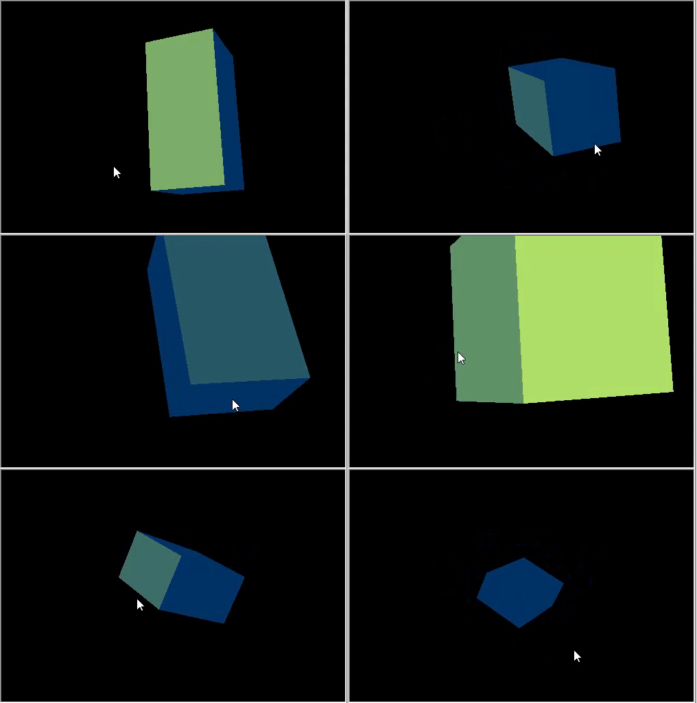
利用鼠标控制相机位置。
纹理是应用于多边形表面,呈现图案或材质的位图图像。 利用纹理可在表面上复现小物体,若是我们用多边形来创建它们,则会需要更多资源。 例如,这可以是对石头、木材、土壤和其他材质的模仿。
CDXMesh 及其子类允许指定纹理。 在标准像素着色器中,纹理会与 DiffuseColor 一起使用。 删除对象动画,并应用石头纹理。 它应该位于终端工作目录的 MQL5\Files 文件夹当中:
   virtual bool      Create(const int width,const int height)
     {
  ...
      //--- set the white color for the non-directional lighting
      m_box.DiffuseColorSet(DXColor(1.0,1.0,1.0,1.0));

      //--- add texture to draw the cube faces
      m_box.TextureSet(m_canvas.DXDispatcher(),"stone.bmp");
      //--- add the cube to the scene
      m_canvas.ObjectAdd(&m_box);
      //--- redraw the scene
      Redraw();
      //--- succeed
      return(true);
      }
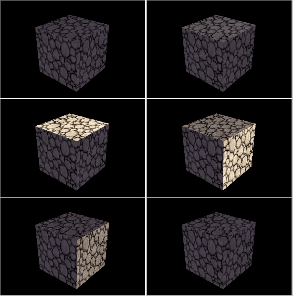
石头材质的立方体。
标准库拥有 DXVertex 顶点类型,其中包含其坐标、计算光照的法线、纹理坐标和颜色。 标准顶点着色器配合顶点类型一同操作。
struct DXVertex
  {
   DXVector4         position;  // vertex coordinates
   DXVector4         normal;    // normal vector
   DXVector2         tcoord;    // face coordinate to apply the texture
   DXColor           vcolor;    // color
  };
MQL5\Include\Canvas\DXDXUtils.mqh 辅助类型包含一套生成基本几何(顶点和索引)图元的方法,以及从 .OBJ 文件里加载 3D 几何图元的方法。
加入创建一个球面和一个圆环,应用相同的石头纹理:
   virtual bool      Create(const int width,const int height)
     {
 ...
      // --- vertices and indexes for manually created objects
      DXVertex vertices[];
      uint indices[];
      //--- prepare vertices and indices for the sphere
      if(!DXComputeSphere(0.3f,50,vertices,indices))
         return(false);
      //--- set white color for the vertices
      DXColor white=DXColor(1.0f,1.0f,1.0f,1.0f);
      for(int i=0; i<ArraySize(vertices); i++)
         vertices[i].vcolor=white;
      //--- create the sphere object
      if(!m_sphere.Create(m_canvas.DXDispatcher(),m_canvas.InputScene(),vertices,indices))
        {
         m_canvas.Destroy();
         return(false);
         }
      //--- set diffuse color for the sphere
      m_sphere.DiffuseColorSet(DXColor(0.0,1.0,0.0,1.0));
      //--- set white specular color
      m_sphere.SpecularColorSet(white);
      m_sphere.TextureSet(m_canvas.DXDispatcher(),"stone.bmp");
      //--- add the sphere to a scene
      m_canvas.ObjectAdd(&m_sphere);
      //--- prepare vertices and indices for the torus
      if(!DXComputeTorus(0.3f,0.1f,50,vertices,indices))
         return(false);
      //--- set white color for the vertices
      for(int i=0; i<ArraySize(vertices); i++)
         vertices[i].vcolor=white;
      //--- create the torus object
      if(!m_torus.Create(m_canvas.DXDispatcher(),m_canvas.InputScene(),vertices,indices))
        {
         m_canvas.Destroy();
         return(false);
         }
      //--- set diffuse color for the torus
      m_torus.DiffuseColorSet(DXColor(0.0,0.0,1.0,1.0));
      m_torus.SpecularColorSet(white);
      m_torus.TextureSet(m_canvas.DXDispatcher(),"stone.bmp");
      //--- add the torus to a scene
      m_canvas.ObjectAdd(&m_torus);
      //--- redraw the scene
      Redraw();
      //--- succeed
      return(true);
      }
为新物体添加动画:
   void              OnTimer(void)
     {
...
      m_canvas.LightDirectionSet(light_direction);
      //--- sphere orbit
      DXMatrix translation;
      DXMatrixTranslation(translation,1.1f,0,0);
      DXMatrixRotationY(rotation,time);
      DXMatrix transform;
      DXMatrixMultiply(transform,translation,rotation);
      m_sphere.TransformMatrixSet(transform);
      //--- torus orbit with rotation around its axis
      DXMatrixRotationX(rotation,time*1.3f);
      DXMatrixTranslation(translation,-2,0,0);
      DXMatrixMultiply(transform,rotation,translation);
      DXMatrixRotationY(rotation,time/1.3f);
      DXMatrixMultiply(transform,transform,rotation);
      m_torus.TransformMatrixSet(transform);
      //--- recalculate the 3D scene and draw it in the canvas
      Redraw();
      }
将更改另存为 Three Objects.mq5,并运行它。
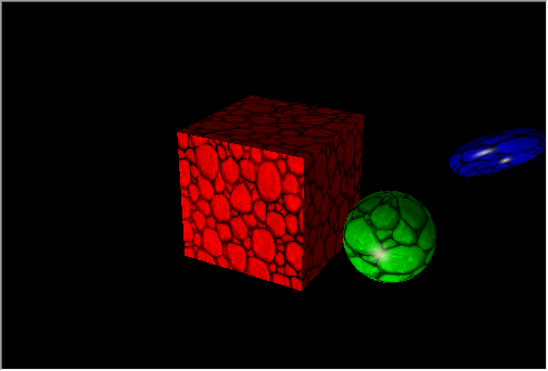
在立方体轨迹上旋转图形。
各种图形通常用于创建报告和分析数据,例如线性图、直方图、饼图等。 MQL5 提供了一套便利的图形库,但是该图形库只能构建 2D 图表。
CDXSurface 类能够依据存储在二维数组中的自定义数据做到表面可视化。 我们查看以下数学函数的示例
z=sin(2.0*pi*sqrt(x*x+y*y))
为绘制表面而创建一个物体,并创建一个数组来存储数据:
   virtual bool      Create(const int width,const int height)
     {
...
      //--- prepare an array to store data
      m_data_width=m_data_height=100;
      ArrayResize(m_data,m_data_width*m_data_height);
      for(int i=0;i<m_data_width*m_data_height;i++)
         m_data[i]=0.0;
      //--- create a surface object
      if(!m_surface.Create(m_canvas.DXDispatcher(),m_canvas.InputScene(),m_data,m_data_width,m_data_height,2.0f,
                           DXVector3(-2.0,-0.5,-2.0),DXVector3(2.0,0.5,2.0),DXVector2(0.25,0.25),
                           CDXSurface::SF_TWO_SIDED|CDXSurface::SF_USE_NORMALS,CDXSurface::CS_COLD_TO_HOT))
        {
         m_canvas.Destroy();
         return(false);
         }
      //--- create texture and reflection
      m_surface.SpecularColorSet(DXColor(1.0,1.0,1.0,1.0));
      m_surface.TextureSet(m_canvas.DXDispatcher(),"checker.bmp");
      //--- add the surface to the scene
      m_canvas.ObjectAdd(&m_surface);
      //--- succeed
      return(true);
      }
将在底面 4x4,高度为 1 的箱体中绘制表面。 纹理维度是 0.25x0.25。
若要制作表面动画,请在标记符号下方添加时间,并通过计时器对其进行刷新。
   void              OnTimer(void)
     {
      static ulong last_time=0;
      static float time=0;
      //--- get the current time
      ulong current_time=GetMicrosecondCount();
      //--- calculate the delta
      float deltatime=(current_time-last_time)/1000000.0f;
      if(deltatime>0.1f)
         deltatime=0.1f;
      //--- increase the elapsed time value
      time+=deltatime;
      //--- remember the time
      last_time=current_time;
      //--- calculate surface values taking into account time changes
      for(int i=0; i<m_data_width; i++)
        {
         double x=2.0*i/m_data_width-1;
         int offset=m_data_height*i;
         for(int j=0; j<m_data_height; j++)
           {
            double y=2.0*j/m_data_height-1;
            m_data[offset+j]=MathSin(2.0*M_PI*sqrt(x*x+y*y)-2*time);
            }
         }
      //--- update data to draw the surface
      if(m_surface.Update(m_data,m_data_width,m_data_height,2.0f,
                          DXVector3(-2.0,-0.5,-2.0),DXVector3(2.0,0.5,2.0),DXVector2(0.25,0.25),
                          CDXSurface::SF_TWO_SIDED|CDXSurface::SF_USE_NORMALS,CDXSurface::CS_COLD_TO_HOT))
        {
         //--- recalculate the 3D scene and draw it in the canvas
         Redraw();
         }
      }
源代码在 3D Surface.mq5 中提供,该程序的示例展示在视频当中。
在本文中,我们研究为了进行直观数据分析,利用 DirectX 函数创建简单几何图形和 3D 动画的功能。 可以在 MetaTrader 5 终端安装目录中找到更复杂的示例:智能交易系统 “Correlation Matrix 3D” 和 “Math 3D Morpher”,以及 “Remnant 3D” 脚本。
MQL5 令您无需使用第三方程序包即可解决重要的算法交易任务:

本社区仅针对特定人员开放
查看需注册登录并通过风险意识测评
5秒后跳转登录页面...
移动端课程
